We are pleased to anounce the release of TwinMesh™ 2019. With our new software version another big and important step in CFD based analysis and design of rotary positive displacement machines is done. The new software version offers developers of lobe, gear and vane pumps as well as of roots type blowers, screw, scroll and wankel machines a further improved workflow and many exciting new features. The enhancements of TwinMesh™ 2019 result in a further streamlined workflow, and again in significantly faster turnaround times for users creating reliable numerical models for CFD analysis of rotary pd machines. Read further for getting information about new features in TwinMesh™ 2019:
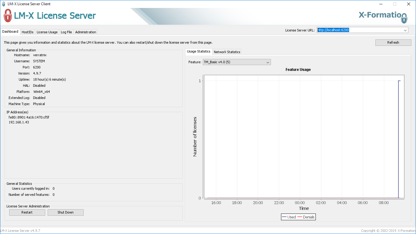
LM-X license manager
TwinMesh™ 2019 now supports floating licenses. LM-X End-user Tools including the LM-X license manager from X-Formation (www.x-formation.com) is used for TwinMesh™ licensing upon release 2019. The LM-X license manager can be installed on both, Windows_x64 systems and on Linux_x64 systems.
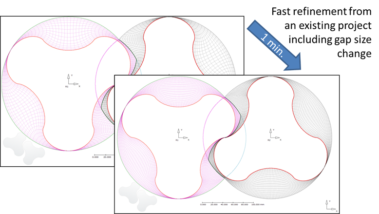
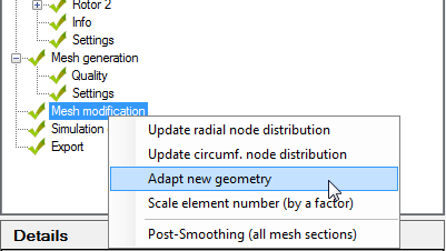
Mesh modification
It is now possible to perform changes to the mesh after its creation for some or all mesh sections. The changes feature mesh refinements towards walls, change of the radial node number, refinement of the circumferential node distribution and scaling of the shaft geometry with a reassignment of the meshes.
Non-reflecting boundary condition
For compressible single phase and multiphase flows, an adapted non-reflecting boundary condition has been developed by CFX Berlin to avoid unwanted acoustical reflections. It is implemented in the fortran routines which are used to import the mesh deformation information by ANSYS™ CFX. This model is comparable to the standard non-reflecting boundary condition of ANSYS™ CFX but without unexpected instabilities. It can be selected in the TwinMesh™ GUI.
New interface model CHT-GGI (beta)
As a beta-feature the new interface model CHT-GGI allows to create a fluid-fluid-solid interface. This is necessary when a solid mesh (casing) is connected to the fluid meshes generated by TwinMesh™ (working chamber) whereas the stator mesh (inlet and outlet fluid volume) is also connected to the TwinMesh™ mesh. This model is available for testing and will be improved in the next releases.
Variable solver timestep (beta)
In all past releases of TwinMesh™ the simulation timestep is calculated from the rotational speed and the angle step between the exported meshes for different rotor positions. It was not possible to reduce the timestep without regenerating the mesh with smaller angle step. It was also not possible to use a variable timestep depending on convergence quality.
To be able to use a timestep independent from the angle step now a new interpolation algorithm is implemented to get meshes between the available meshes of TwinMesh™. The fortran routine will do the interpolation while a simulation is running.
Variable rotational speed and direction (beta)
Together with the new mesh interpolation feature the rotational speed of a machine can be varied. This function enables simulations with rotational speed of 0 and even changes in the rotational direction, which for specific applications is esssential.
Consideration of rotor deformation
Shaft deflection and thermal deformation can be considered. The shaft deflection is defined by a table with offset values for X and Y of the rotor axis position depending on the Z-coordinate. The thermal deformation is defined by a table with offset values for normal scaling of the rotor depending on the Z-coordinate. These features have some restrictions to keep the mesh quality as good as possible.
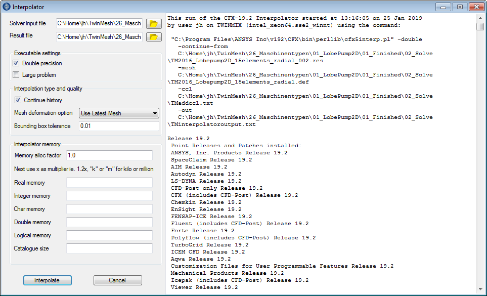
Easy interpolation of simulation results
This feature now allows an interpolation of simulation results onto a new definition file with additional options that are not available in the standard interpolator GUI of the ANSYS™ CFX Solver but necessary for a multi-configuration restart of a TwinMesh™ case. It uses the standard interpolator of ANSYS™ CFX with less manual effort.
- Add CCLs for advanced settings directly in TwinMesh™
- Additional mesh quality criteria
- Support of up to 16 cores
- Improved selection capabilities
- Speedup of the pre-smoothing process
- Speedup of the post smoothing process (beta)
- Save view
The automatic setup creation of TwinMesh™ for ANSYS™ CFX is easy to use and allows to setup the basic options (numerical models, boundary conditions, etc.) to run simulations for the specified type of engine. To use TwinMesh™ for the simulation setup without manual modification in ANSYS™ CFX-Pre a CCL text now can be added to the TwinMesh™ project. This allows for e. g. change of fluid properties, change of numerical model options in detail, etc.
To verify the quality of volume discretization a new option is available (“Relative gap size error”). It shows the deviation between the original geometry and the generated mesh based on the distance from the rotor to the casing curve.
TwinMesh™ 2019 now supports the usage of up to 16 local cores for the meshing process.
Select multiple curve segments by double clicking on a curve with comparable size to the others. Use window selection by holding the left mouse button and move the mouse over the selection area.
The pre-smoothing process now needs less iterations especially for cases with large number of elements in circumferential direction.
For the post-smoothing process a multigrid option is now available (not default) which makes this operation much faster.
The current model view of TwinMesh can be saved as a picture.
Enjoy working with this great new release of the industry leading software for structured grid generation for rotary positive displacement machines! In order to get the new version of TwinMesh™ please contact us or your local TwinMesh™ reseller.
